Fluidized bed reactor
A fluidized bed reactor (FBR) is a type of reactor device that can be used to carry out a variety of
multiphase chemical reactions. In this type of reactor, a fluid (gas or liquid) is passed through a granular solid material (usually a catalyst possibly shaped as tiny spheres) at high enough velocities to suspend the solid and cause it to behave as though it were a fluid. This process, known as fluidization, imparts many important advantages to the FBR. As a result, the fluidized bed reactor is now used in many industrial applications.

The solid substrate (the catalytic material upon which chemical species react) material in the fluidized bed reactor is typically supported by a porous plate, known as a distributor.[1] The fluid is then forced through the distributor up through the solid material. At lower fluid velocities, the solids remain in place as the fluid passes through the voids in the material. This is known as a packed bed reactor. As the fluid velocity is increased, the reactor will reach a stage where the force of the fluid on the solids is enough to balance the weight of the solid material. This stage is known as incipient fluidization and occurs at this minimum fluidization velocity. Once this minimum velocity is surpassed, the contents of the reactor bed begin to expand and swirl around much like an agitated tank or boiling pot of water. The reactor is now a fluidized bed. Depending on the operating conditions and properties of solid phase various flow regimes can be observed in this reactor.
USES
Today fluidized bed reactors are still used to produce gasoline and other fuels, along with many other chemicals. Many industrially produced polymers are made using FBR technology, such as rubber,
vinyl chloride, polyethylene, styrenes, and polypropylene.[7] Various utilities also use FBR's for
coal gasification, nuclear power plants, and water and waste treatment settings. Used in these applications, fluidized bed reactors allow for a cleaner, more efficient process than previous standard reactor technologies.[4]
Advantages
The increase in fluidized bed reactor use in today's industrial world is largely due to the inherent advantages of the technology.[8]
- Uniform Particle Mixing: Due to the intrinsic fluid-like behavior of the solid material, fluidized beds do not experience poor mixing as in packed beds. This complete mixing allows for a uniform product that can often be hard to achieve in other reactor designs.
- Uniform Temperature Gradients: Many chemical reactions require the addition or removal of heat. Local hot or cold spots within the reaction bed, often a problem in packed beds, are avoided in a fluidized situation such as an FBR.
- Ability to Operate Reactor in Continuous State: The fluidized bed nature of these reactors allows for the ability to continuously withdraw product and introduce new reactants into the reaction vessel.
Air-lift fermenter

Air-lift fermenter is an efficient contactor for the reactions involved gases, liquids and solids. There are two types of air-lift fermenters which are the internal loop and the external loop. The internal loop has a draft tube in its inner tube, in which the up-flowing gasses liquid and the down-flowing liquid is separated by the draft tube. Draft tubes are used in some processes to promote better mass transfer, mixing and inducing circulatory motion to reduce bubble coalescence. The external loop has two streams flow in two separate pipes connected at top and bottom. In this way, the air-lift fermenters improve the circulation and oxygen transfer and equalize shear forces in the reactor. Both of the internal and external loop air-lift fermenters have been investigated to the hydrodynamic behaviour and other design factors.
Unlike the mechanical agitation system, air-lift fermenters do not have motor, shaft and impeller blades. As such, the mixture inside the fermenters is agitated by injecting air from the bottom of the tube. Sterile atmospheric air is injected into the fermenters if the microorganism is aerobic, while for the anaerobic microorganism is fed with inert gas. Mixing in air-lift fermenters is very gentle hence it is suitable for batch culture of shear sensitive cells and tissues such as the mammalian and plant cells. Likewise, high shearing stress causes damage to cells could be avoided. Batch culture of plant and animal cells can be cost intensive. However, in cases where the demand for the plant or animals culture products is low and batch cycles are long, the high capital cost can exclude the economical production. One of the application of air-lift fermenters is the large scale production of monoclonal antibodies.
Plug flow reactor model
The plug flow reactor model (PFR, sometimes called continuous tubular reactor, CTR, or piston flow reactors) is a model used to describe
chemical reactions in continuous, flowing systems of cylindrical geometry. The PFR model is used to predict the behavior of
chemical reactors of such design, so that key reactor variables, such as the dimensions of the reactor, can be estimated.
chemical reactions in continuous, flowing systems of cylindrical geometry. The PFR model is used to predict the behavior of
chemical reactors of such design, so that key reactor variables, such as the dimensions of the reactor, can be estimated.
Fluid going through a PFR may be modeled as flowing through the reactor as a series of infinitely thin coherent "plugs", each with a uniform composition, traveling in the axial direction of the reactor, with each plug having a different composition from the ones before and after it. The key assumption is that as a plug flows through a PFR, the fluid is perfectly mixed in the radial direction but not in the axial direction (forwards or backwards). Each plug of differential volume is considered as a separate entity, effectively an infinitesimally small continuous stirred tank reactor,
limiting to zero volume. As it flows down the tubular PFR, the residence time ( ) of the plug is a function of its position in the reactor.
limiting to zero volume. As it flows down the tubular PFR, the residence time (
[edit] Operation and uses
PFRs are used to model the chemical transformation of compounds as they are transported in systems resembling "pipes". The "pipe" can represent a variety of engineered or natural conduits through which liquids or gases flow. (e.g. rivers, pipelines, regions between two mountains, etc.)
An ideal plug flow reactor has a fixed residence time: Any fluid (plug) that enters the reactor at time  will exit the reactor at time
  , where is the residence time of the reactor. The residence time distribution function is therefore a
dirac delta function at. A real plug flow reactor has a residence time distribution that is a narrow pulse around the
mean residence time distribution.
dirac delta function at
mean residence time distribution.
A typical plug flow reactor could be a tube packed with some solid material (frequently a catalyst). Typically these types of reactors are called packed bed reactors or PBR's. Sometimes the tube will be a tube in a shell and tube
heat exchanger.
heat exchanger.
Plug flow reactors have a high volumetric unit conversion, run for long periods of time without maintenance, and the heat transfer rate can be optimized by using more, thinner tubes or fewer, thicker tubes in parallel. Disadvantages of plug flow reactors are that temperatures are hard to control and can result in undesirable temperature gradients. PFR maintenance is also more expensive than CSTR maintenance. [2]
Through a recycle loop a PFR is able to approximate a CSTR in operation. This occurs due to a decrease in the concentration change due to the smaller fraction of the flow determined by the feed; in the limiting case of total recycling, infinite recycle ratio, the PFR perfectly mimics a CSTR.
[edit] Applications
Plug flow reactors are used for some of the following applications:
- Large-scale reactions
- Fast reactions
- Homogeneous or heterogeneous reactions
- Continuous production
- High-temperature reactions
What is a membrane reactor?
A membrane reactor is really just a plug-flow reactor that contains an additional cylinder of some porous material within it, kind of like the tube within the shell of a shell-and-tube heat exchanger. This porous inner cylinder is the membrane that gives the membrane reactor its name.
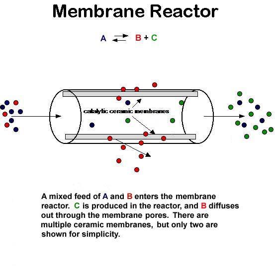
The membrane is a barrier that only allows certain components to pass through it. The selectivity of the membrane is controlled by its pore diameter, which can be on the order of Angstroms, for microporous layers, or on the order of microns for macroporous layers.
Why use a membrane reactor?
Membrane reactors combine reaction with separation to increase conversion. One of the products of a given reaction is removed from the reactor through the membrane, forcing the equilibrium of the reaction "to the right" (according to Le Chatelier's Principle), so that more of that product is produced.
Membrane reactors are commonly used in dehydrogenation reactions (e.g., dehydrogenation of ethane), where only one of the products (molecular hydrogen) is small enough to pass through the membrane. This raises the conversion for the reaction, making the process more economical.
Chemical reactors making use of membranes are usually referred to as membrane reactors. The membrane can be used for different tasks:
- Separation
- Selective extraction of reactants
- Retention of the catalyst
- Distribution/dosing of a reactant
- Catalyst support (often combined with distribution of reactants)
Membrane reactors are an example for the combination of two
unit operations in one step e.g. membrane filtration with the chemical reaction.
unit operations in one step e.g. membrane filtration with the chemical reaction.
Hollow fiber reactors
In order to more closely approximate in vivo cell growth conditions, Richard Knazek developed the hollow fiber bioreactor (HFBR) in 1972 (1). The HFBR system is a high-density, continuous-perfusion culture system. It is a well-established system for the production of secreted proteins from hybridoma, Chinese hamster ovary cells (CHO), human embryonic kidney (HEK) 293 and other mammalian and insect cells. The primary advantage is that it is possible to culture large numbers of cells at high density, resulting in product accumulating to very high concentrations. Up until now, the application of HFBR technology has been limited to laboratory scale applications. HFBRs provide some features that are advantageous in biopharmaceutical manufacturing, such as continuous, modular, flexible manufacturing formats employing compact and disposable systems. There is also growing interest in perfusion-based bioproduction protocols (2). FiberCell Systems has developed a large-scale HFBR system that brings the benefits of hollow fiber cell culture to the bio-production arena.
HFBRs consist of thousands of semi-permeable hollow fibers in a parallel array within a tubular housing or cartridge, fitted with inlet and outlet ports. These fiber bundles are potted at each end so that any liquid entering the ends of the cartridge will necessarily flow through the interior of the fibers. Cells are generally seeded within the cartridge, but outside of the hollow fibers in what is referred to as the extra capillary space.Culture media is pumped inside the hollow fibers, allowing dissolved gas, nutrients, and waste products to diffuse across the fiber walls. Once having passed through the cartridge, the culture medium is oxygenated and returned to the cartridge.
Hollow fibre bioreactor, in which cells are kept inside the hollow, porous fibres, and the culture medium is circulated outside the reactor. The fibres let nutrients in and products out (as they are in solution), but do not allow the passage of cells. Hollow fibre bioreactors are very effective for maintaining mammalian cells in culture because they have a very large surface area for the cells to grow on without needing a large reactor to hold them, and because the nutrient reaching the cells can be kept fresh. The reactor also provides an easy way of removing the product that the cells are making: such as monoclonal antibodies. Hollow fibre reactors are less use when the cells themselves have to grow, because it is hard to get at the inside of the fibre to remove surplus cells.
Biosensor
A biosensor is an analytical device consisting of an immobilized layer of biological material (e.g. enzyme, antibody, organelle, hormones, nucleic acids or whole cells) in the intimate contact with a transducer i.e. sensor (a physical component) which analyses the biological signals and converts into an electrical signal (Gronow, 1984). A sensor can be anything, a single carbon electrode, an ion-sensitive electrode, oxygen-electrode, a photocell or a thermistor.
The principle of the biosensor is quite simple (Fig. 17.6). The biological material is immobilized as described earlier on the immobilization support, the permeable membrane, in the direct vicinity of a sensor. The substances to be measured pass through the membrane and interact with the immobilized material and yield the product. A product (i.e. the monitored substrate) may be heat, gas (oxygen), electrons, hydrogen ions or the product of ammonium ions. The product passes through another membrane to the transducer. The transducer converts product into an electric signal which is amplified. The signal processing equipment converts the amplified signals into a display most commonly the electric signal which can be read out and recorded.
Types of biosensor
Biosensor are of different types based on the use of different biological material and sensor devices; a few of them are discussed below:
(i) Electro-chemical biosensor. This type of biosensor has been developed by using electronic devices such as field effect transmitors or light emitting diode; the former measures charge accumulation on their surface and the later photoresponse generated in a silica based chip as an alternating current. Hence, the field effect transmitor measures a biochemical reaction at the surface and induce into current (Gronow et al, 1988). Moreover, the field effect transmitors can be modified to ion sensitive, enzyme sensitive or antibody sensitive ones by using selective ions, enzymes or antibodies respectively.
(ii) Amperometric biosensor. Amperometric biosensors are those which measure the reaction of anylate with enzyme and generate electrons directly or through a mediator. The amperometric biosensors contain either enzyme-electrode or without a mediator, or chemically modified electrodes. The oxygen and peroxide based biosensor and others (Table 17.4) discussed earlier are enzyme -electrode biosensor. Some advancement has been brought into this type of biosensor by using a mediator. In addition, more advanced types are the direct electron transfer systems.
(iii) Thermistor containing biosensor. Thermistor is used to record even a small temperature changes (between 0.1-0.001°C) during biochemical reactions. By immobilizing enzymes like cholesterol oxidase, glucose oxidase, invertase, tyrosinase, etc. thermistors have been developed (Gronow et al, 1988). Moreover, thermistors are also employed for the study of antigen- antibody with very high sensitivity (10-13 mol dm-3) in case of thermometric Enzyme Linked Immunoabsorbant Assay (ELISA).
(iv) Bioaffinity sensor : Bioaffinity sensors are developed recently. It measures the concentration of the determinants, i.e. substrates based on equilibrium binding. This shows a high degree of selectivity. These are of diverse nature because of the use of radiolabelled, enzyme labeled or fluorescence-labeled substance.
(iv) Bioaffinity sensor : Bioaffinity sensors are developed recently. It measures the concentration of the determinants, i.e. substrates based on equilibrium binding. This shows a high degree of selectivity. These are of diverse nature because of the use of radiolabelled, enzyme labeled or fluorescence-labeled substance.
(v) Whole cell biosensors — (Microbial Biosensors). In this device, either immobilized whole cell of microorganisms or their organelles are used. These react with a large number of substrates and show generally slow response (Corcoran and Rechnitz, 1985). Immobilized Azotobacter vinelandii coupled with ammonia electrode shows sensitivity range between 10-5 and 8 x 10 mol dm-3. It measures the concentration of nitrate within 5-10 min-2.
(vi) Opto-electronic biosensor. In these biosensors either enzymes or antibodies are immobilized on the surface of a membrane. For measuring color, biosensor with enzyme and dye is immobilized to a membrane. When a substrate is catalyzed to yield product, changes in pH of the medium occur. This results in changes in dye - membrane complex. These changes in color are measured by using a light emitting diode and a photodiode (Gronow et al, 1988).
Applications of biosensor
In the beginning biosensor was applied in the field of medicine and industry. But in recent years, biosensors are becoming popular in many areas due to the small size, rapid and easy handling, low cost, and greater sensitivity and selectivity. Application of biosensor in some of the areas is described as below:
(i) Uses in medicine and health. Biosensors have tremendous potential for its application in the field of medical science. In 1979, the first glucose analyzer using biomolecule for the detection of blood glucose was commercialized by Yellow Springs Instruments Co., USA. A device, a minipump filled with insulin, has been constructed to deliver insulin to diabetics based on glucose levels of blood. When biosensor provides informations, the device delivers accurate amount of insulin required by the diabetics. Mitomycin, an aflatoxin, causes cancer in inborne infants. Therefore, mutagenicity of such chemicals can be detected by using the biosensor. Similarly, any other abnormal toxic substance produced in body due to infectious disease can also be detected.
(ii) Uses in pollution control. Biosensors are very helpful in environmental minitoring and pollution control, since they can be miniaturized and automated. As far as quality control of drinking water is concerned, the minitoring biosensors are successful in monitoring of pesticides in water. In Japan, a biosensor coupled with oxygen electrode and immobilized Trichosporon cutaneum is used for measuring biological oxygen demand (BOD) (Gronow et al, 1988).
(iii) Uses in industry. Generally, spectrophotometer and autoanalyzer are used to estimate the substrates utilized and the products formed in the fermented broth. In addition, there are a lot of problems associated with these. So the biosensors can be designed to measure the fermentation products to improve the feed back control, to carry out rapid sampling and rejection of below standard raw materials to improve the efficiency of workers. Isaokarube and coworkers of Tokyo University Research Centre of Advance Science & Technology have recently developed an ion sensitive field effect transistor (ISFET). This device is highly sensitive to change the ion concentration. Using this biosensor, it is possible to measure the odor, freshness and taste of foods. In dertemining fish freshness either ATPase, aminoxidase or putrescine oxidase is used. ATPase detects, the presence of ATP in fish muscle. As ATP is not present in staled food, therefore, signals do not occur. Recently, a biosensor has been developed at Cransfield Institute of Technology, UK which measures cholesterol levels in butter. The enzyme cholesterol oxidase, when immobilized on the electrodes, reacts with cholesterol of food.
(iv) Biosensor in military. The darker side of biosensor application is to provide support to military with such a biosensor that can detect toxic gases including chemical warfare agents. Such biosensors have advantages over the traditional methods of sensing of chemicals.
Process Flow Diagrams
Because of the complexity of large-scale manufacturing
processes, communicating information about these
systems requires special methods. Flow diagrams or flow sheets
are simplified pictorial representations of processes and are
used to present relevant process information and data. Flow
sheets vary in complexity from simple block diagrams to highly
complex schematic drawings showing main and auxiliary
process equipment such as pipes, valves, pumps and by-pass
loops.
Figure 3.13 is a simplified process flow diagram showing
the major operations for production of the antibiotic, bacitracin.
This qualitative flow sheet indicates the flow of materials,
the sequence of process operations, and the principal equipment
in use. When flow diagrams are applied in calculations,
the operating conditions, masses and concentrations of
material handled by the process are also specified. An example
is Figure 3.14, which represents recovery operations for
2,3-butanediol produced commercially by fermentation of
whole wheat mash. The quantities and compositions of
streams undergoing processes such as distillation, evaporation,
screening and drying are shown to allow calculation of product
yields and energy costs.
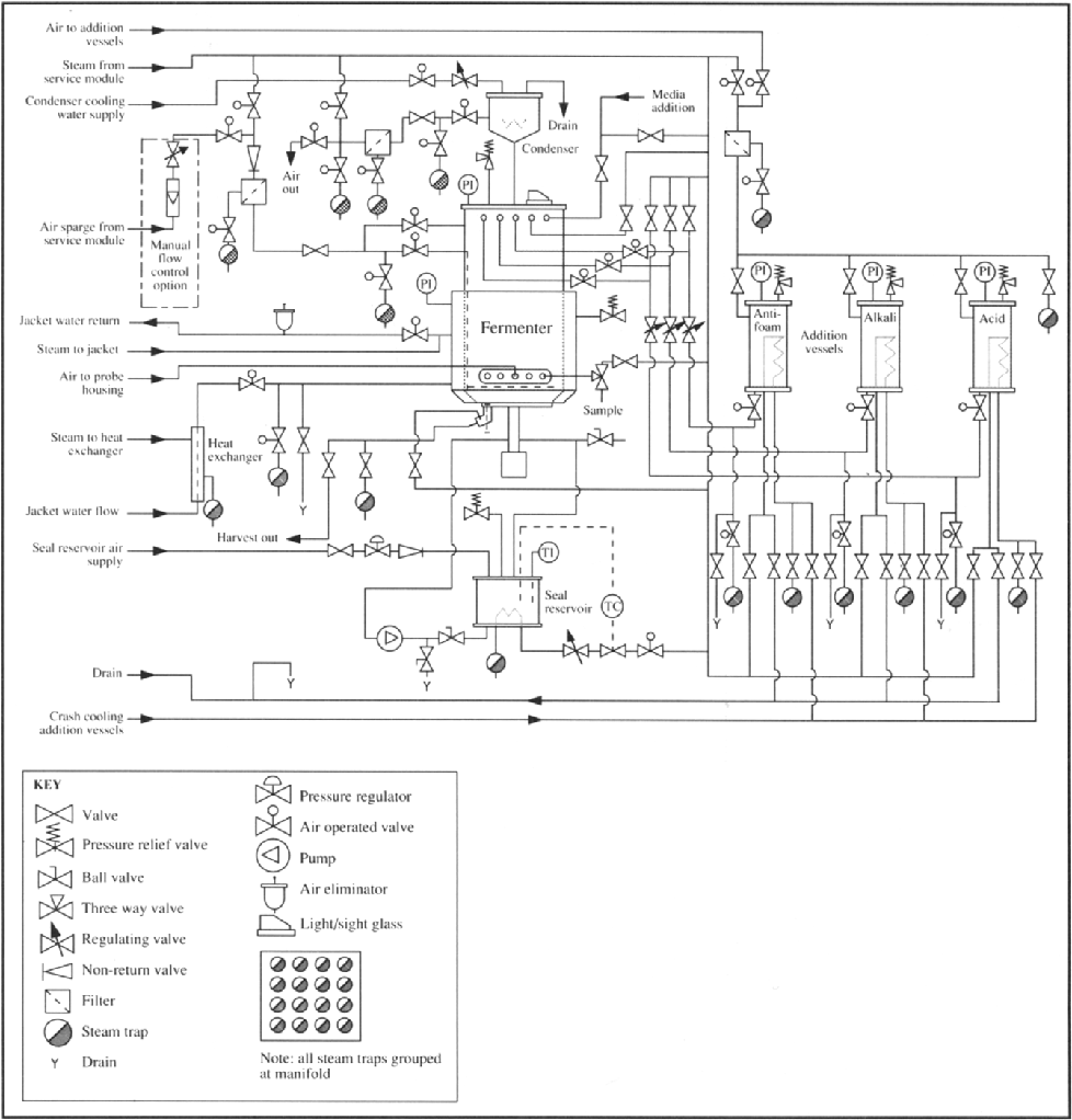
Detailed engineering flowsheets such as Figure 3.15 are
useful for plant construction work and trouble-shooting
because they show all piping, valves, drains, pumps and safety
equipment. Standard symbols are adopted to convey the information
as concisely as possible. Figure 3.15 represents a
pilot-scale fermenter with separate vessels for antifoam, acid
and alkali. All air, medium inlet and harvest lines are shown, as
are the steam and condensate-drainage lines for in situ steam
sterilisation of the entire apparatus.
In addition to those illustrated here, other specialised types
of flow diagram are used to specify instrumentation for process
control networks in large-scale processing plants, and for utilities
such as steam, water, fuel and air supplies. We will not be
applying complicated or detailed diagrams such as Figure 3.15
in our analysis of bioprocessing; their use is beyond the scope
of this book. However, simplified versions of flow diagrams
are extremely useful, especially for material- and energybalance
calculations; we will be applying block diagram flow
sheets in Chapters 4-6 for this purpose. You should become
familiar with flow diagrams for showing data and other process
information.
Monitoring and Control of Bioreactors
The environment inside bioreactors should allow optimal
catalytic activity. Parameters such as temperature, pH,
speed and sparging rate have a significant effect on the outcome
of fermentation and enzyme reactions. To provide the
desired environment, system properties must be monitored
and control action taken to rectify any deviations from the
desired values. Fermentation monitoring and control is an
active area of research aimed at improving the performance of
bioprocesses and achieving uniform and reliable fermenter
operation.
Various levels of process control exist in the fermentation
industry. Manual control is the simplest, requiring a human
operator to manipulate devices such as pumps, motors and
valves. Automatic feedback control is used to maintain parameters
at specified values. With increasing application of
computers in the fermentation industry, there is also scope for
implementing advanced control and optimisation strategies
based on fermentation models.
13.4.1 Fermentation Monitoring
Any attempt to understand or control the state of a fermenta
tion depends on knowledge of critical variables which affect
the process. These parameters can be grouped into three categories:
physical, chemical and biological. Examples of process
variables in each group are given in Table 13.1. Many of the
physical measurements listed are well established in the fermentation
industry; others are currently being developed or
are the focus of research into new instrumentation.
Despite the importance of fermentation monitoring,
industrially-reliable instruments and sensors capable of rapid,
accurate and direct measurements are not available for many
process variables. For effective control of fermentations based
on measured data, the time taken to complete the measure-
ment should be compatible with the rate of change of the variable
being monitored.
13.4.2 Measurement Analysis
Any attempt to analyse or apply the results of fermentation
monitoring must consider the errors and spurious or transient
results incorporated into the data. Noise and variability are
particular problems with certain fermentation measurements;
for example, probes used for pH and dissolved-oxygen measurements
are exposed to rapid fluctuations and heterogeneities in
the broth so that noise can seriously affect the accuracy of
point readings. Figure 13.16 shows typical results from online
measurement of dilution rate and carbon dioxide
evolution in a production-scale fermenter; in many cases, signal
conditioning or smoothing must be carried out to reduce the
noise in these data before they can be applied for process control
or modelling. Most modern data acquisition and logging
systems contain facilities for signal conditioning. Unwanted
pseudo-random noise can be filtered out using analogue filter
circuits or by averaging values over successive measurements.
Alternatively, unfiltered signals can be digitised and filtering
algorithms applied using computer software. Measurement
drift cannot be corrected using electronic circuitry; instruments
must be periodically recalibrated during long
fermentations to avoid loss of accuracy.
13.4.3 Fault Analysis
Faults in reactor operation affect 15-20% of fermentations
[25]. Fermentation measurements can be used to detect faults;
for example, signals from a flow sensor could be used to detect
blockages in a pipe and trigger an alarm in the factory control
room. Normally however, the sensors themselves are the most
likely components to fail; rates of failure of some fermentation
instruments are listed in Table 13.2. Failure of a sensor might
be detected as an unexpected change or rate of change in its
signal, or a change in the noise characteristics. Several
approaches can be used to reduce the impact of faults on largescale
fermentations; these include comparison of current
measurements with historical values, cross-checking between
independent measurements, using multiple and back-up sensors,
and building hardware redundancy into computer
systems and power supplies.
13.4.4 Process Modelling
In modern approaches to fermentation control, a reasonably
accurate mathematical model of the reaction and reactor
environment is required. Using process models, we can
progress beyond environmental control ofbioreactors into the
realm of direct biological control. Development of fermentation
models is aided by information from measurements taken
during process operation.
Models are mathematical relationships between variables.
Traditionally, models are based on a combination of'theoretical'
relationships which provide the structure of the model,
and experimental observations which provide the numerical
values of coefficients. For biological processes, specifying the
model structure can be difficult because of the complexity of
cellular processes and the large number of environmental factors
which affect cell culture. Usually, bioprocess models are
much-simplified approximate representations deduced from
observation rather than from theoretical laws of science. As an
example, a frequently-used mathematical model for batch fermentation
consists of the Monod equation for growth and an
expression for rate of substrate consumption as a function of
biomass concentration:
13.4.5 State Estimation
As described in Section 13.4.1, it is not possible to measure
on-line all the key variables or states of a fermentation process
Often, considerable delays are involved in off-line measurement
of important variables such as biomass, substrate and
product concentrations. Such delays make effective control of
the reactor difficult if control action is dependent on the value
of these parameters, but must be undertaken more quickly
than off-line analysis allows. One approach to this problem is
to use available on-line measurements in conjunction with
mathematical models of the process to estimate unknown
variables. The computer programs and numerical procedures
developed to achieve this are called software sensors, estimators
or observers. The Kalman filter is a well-known type of observer
applicable to linear process equations; non-linear systems can
be treated using the extendedKalmanfllter [26]. The success of
Kalman filters and other observers depends largely on the
accuracy and robustness of the process model used.
13.4.6 Feedback Control
Let us assume we wish to maintain the pH in a bioreactor at a
constant value against a variety of disturbances, for example,
from metabolic activity. One of the simplest control schemes
is a conventional feedback control loop, the basic elements of
which are shown in Figure 13.18. A measurement device
senses the value of the pH and sends the signal to a controller.
At the controller, the measured value is compared with the
desired value known as the set point. The deviation between
measured and desired values is the error, which is used by the
controller to determine what action must be taken to correct
the process. The controller may be a person who monitors the
process measurements and decides what to do; more often the
controller is an automatic electronic, pneumatic or computer
device. The controller produces a signal which is transmitted
to the actuator, which executes the control action. In a typical
system for pH control, an electrode would serve as the measurement
device and a pump connected to a reservoir of acid or
alkali as the actuator. Simple on-offcontrol is generally sufficient
for pH; if the measured pH falls below the set point, the
controller switches on the pump which adds alkali to the fermenter.
When enough alkali is added and the pH returned to
the set value, the pump is switched off. Small deviations from
the set point are usually tolerated in on-off control to avoid
rapid switching and problems due to measurement delay.
13.4.7 Indirect Metabolic Control
Maintaining particular values of temperature or pH is a rather
indirect approach to bioreactor control; the wider objective is
to optimise performance of the catalyst and maximise production
of the desired product. Certain derived variables such as
the oxygen-uptake rate and respiratory quotient can be calculated
from on-line fermentation measurements; these variables
reflect to some extent the biological state of the culture. It can
be advantageous to base control actions on deviation of these
metabolic variables from desired values rather than on environmental
conditions.
13.4.8 Programmed Control
Because of the inherent time-varying character of batch and
fed-batch fermentations, maintaining a constant environment
or constant values of metabolic variables is not always the optimal
control strategy. Depending on the process, changes in
variables such as pH and temperature at critical times can
improve production rate and yield. Varying the rate of the feed
is important in fed-batch bakers' yeast fermentations to minimise
the Crabtree effect and maximise biomass production.
Feed rate is also manipulated in E. coli fermentations to reduce
by-product synthesis. In secondary-metabolite fermentations,
specific growth rate should be high at the start of the culture
but, at high cell densities, different conditions are required
to slow growth and stimulate product formation. Similar
strategies are needed to optimise protein synthesis from
recombinant organisms. Expression of recombinant product
is usually avoided at the start of the culture because cell growth
is adversely affected; however, later in the batch an inducer is
added to switch on protein synthesis.
Immobilized Enzyme Reactor
DFRL, DRDO developed a bio-reactor to make the hydrolysis of the lactose a cost effective method, novel and simple to operate either in batch or continuous mode. The bio-catalyst if reused for several times can contribute to improve the cost benefit ratio. The lactose hydrolysis is carried out either at 5-150 C or > 350 C drastically reduce the microbial contamination in the bio-reactor developed.
The bio-reactor can hold immobilized enzyme/whole cell catalysts at high density and varying operational temperature. This bio-reactor is able to retain immobilized bio-catalysts prepared in form of granules, blocks, or fibrous materials. This instrument can provide long term mechanical and biochemical stability to immobilized enzyme preparations and effective hydrolysis of lactose in closed loop. The system achieved hydrolysis purity of 98% in milk. The economy and process efficiency of lactose hydrolysis in milk improved using this continuous flow bio-reactor. The technology is economical and micro biologically safe.
ETHANOL PRODUCTION
This process flow diagram shows the basic steps in production of ethanol from cellulosic biomass. While cellulosic ethanol is not yet commercial in the U.S., it has been demonstrated by several groups, and commercial facilities are being planned in North America. Note that there are a variety of options for pretreatment and other steps in the process and that some specific technologies combine two or all three of the hydrolysis and fermentation steps within the shaded box. Chart courtesy of the National Renewable Energy Laboratory.
| ||||||||||
Section: BIOFUELS
| ||||||||||
The Production of Ethanol from Cellulosic Biomass
| ||||||||||
 | ||||||||||
Hydrolysis is the chemical reaction that converts the complex polysaccharides in the raw feedstock to simple sugars. In the biomass-to-bioethanol process, acids and enzymes are used to catalyze this reaction.
| ||||||||||
Fermentation is a series of chemical reactions that convert sugars to ethanol. The fermentation reaction is caused by yeast or bacteria, which feed on the sugars. Ethanol and carbon dioxide are produced as the sugar is consumed.
| ||||||||||
Process Description. The basic processes for converting sugar and starch crops are well-known and used commercially today. While these types of plants generally have a greater value as food sources than as fuel sources there are some exceptions to this. For example, Brazil uses its huge crops of sugar cane to produce fuel for its transportation needs. The current U.S. fuel ethanol industry is based primarily on the starch in the kernels of feed corn, America's largest agricultural crop.
| ||||||||||
1. Biomass Handling. Biomass goes through a size-reduction step to make it easier to handle and to make the ethanol production process more efficient. For example, agricultural residues go through a grinding process and wood goes through a chipping process to achieve a uniform particle size.
| ||||||||||
2. Biomass Pretreatment. In this step, the hemicellulose fraction of the biomass is broken down into simple sugars. A chemical reaction called hydrolysis occurs when dilute sulfuric acid is mixed with the biomass feedstock. In this hydrolysis reaction, the complex chains of sugars that make up the hemicellulose are broken, releasing simple sugars. The complex hemicellulose sugars are converted to a mix of soluble five-carbon sugars, xylose and arabinose, and soluble six-carbon sugars, mannose and galactose. A small portion of the cellulose is also converted to glucose in this step.
| ||||||||||
3. Enzyme Production. The cellulase enzymes that are used to hydrolyze the cellulose fraction of the biomass are grown in this step. Alternatively the enzymes might be purchased from commercial enzyme companies.
| ||||||||||
4. Cellulose Hydrolysis. In this step, the remaining cellulose is hydrolyzed to glucose. In this enzymatic hydrolysis reaction, cellulase enzymes are used to break the chains of sugars that make up the cellulose, releasing glucose. Cellulose hydrolysis is also called cellulose saccharification because it produces sugars.
| ||||||||||
5. Glucose Fermentation. The glucose is converted to ethanol, through a process called fermentation. Fermentation is a series of chemical reactions that convert sugars to ethanol. The fermentation reaction is caused by yeast or bacteria, which feed on the sugars. As the sugars are consumed, ethanol and carbon dioxide are produced.
| ||||||||||
6. Pentose Fermentation. The hemicellulose fraction of biomass is rich in five-carbon sugars, which are also called pentoses. Xylose is the most prevalent pentose released by the hemicellulose hydrolysis reaction. In this step, xylose is fermented using Zymomonas mobilis or other genetically engineered bacteria.
| ||||||||||
7. Ethanol Recovery. The fermentation product from the glucose and pentose fermentation is called ethanol broth. In this step the ethanol is separated from the other components in the broth. A final dehydration step removes any remaining water from the ethanol.
| ||||||||||
8. Lignin Utilization. Lignin and other byproducts of the biomass-to-ethanol process can be used to produce the electricity required for the ethanol production process. Burning lignin actually creates more energy than needed and selling electricity may help the process economics.
| ||||||||||
Converting cellulosic biomass to ethanol is currently too expensive to be used on a commercial scale. Researchers are working to improve the efficiency and economics of the ethanol production process by focusing their efforts on the two most challenging steps:
| ||||||||||
• Cellulose hydrolysis. The crystalline structure of cellulose makes it difficult to hydrolyze to simple sugars, ready for fermentation. Researchers are developing enzymes that work together to efficiently break down cellulose.
| ||||||||||
• Pentose fermentation. While there are a variety of yeast and bacteria that will ferment six-carbon sugars, most cannot easily ferment five-carbon sugars, which limits ethanol production from cellulosic biomass. Researchers are using genetic engineering to design microorganisms that can efficiently ferment both five- and six-carbon sugars to ethanol at the same time.
|
No comments:
Post a Comment
Note: Only a member of this blog may post a comment.